|
|
|
|
|||||
|
|
|
|
|
| |||
|
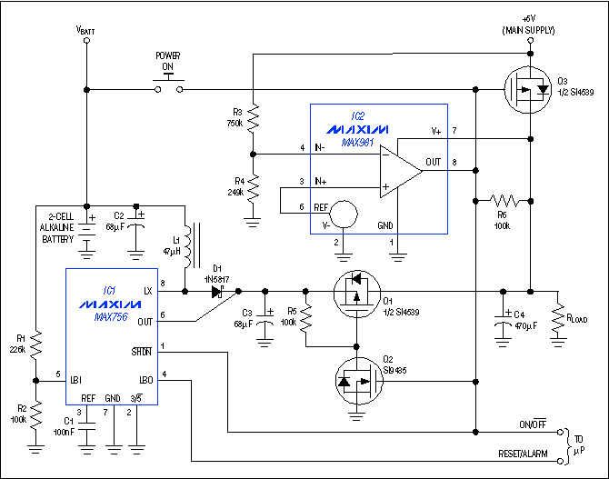
The circuit shown in Figure 1 is a complete portable-equipment power supply suitable for systems that can be plugged into a docking station. When the main supply is removed or falls out of regulation, selector circuitry automatically switches the load to a regulated switch-mode supply powered by a backup battery. The system flags a controlling processor when this switchover occurs, and it also issues a warning when the backup-battery voltage falls below a programmable threshold.  Figure 1. This power supply makes VBATT available to power the load until the main +5V supply is connected. It then automatically disconnects the load from VBATT and connects it to the +5V supply. Two discharged alkaline or nickel-cadmium cells are sufficient to operate the DC-DC backup converter (IC1 and associated components). This converter produces a pin-selectable 5V or 3.3V output voltage with a 200mA output current. The presence of the main supply voltage (+5V) deactivates the backup supply: the output of an ultra-low-power comparator/reference device (IC2) is low in the presence of the +5V supply, and it connects the load and supply by turning on p-channel MOSFET Q3. IC2's low output also places IC1 in shutdown and turns off n-channel MOSFET Q2. C3 is charged by the main supply via the parasitic diode in Q1, so R5 pulls the Q1 gate high, turning off that device as well. If the +5V supply fails or falls out of regulation (as defined by a 4.75V threshold determined by R3 and R4), the IC2 output goes high, disconnects the main supply by turning off Q3, turns on the backup supply by pulling IC1 out of shutdown, and connects the backup voltage and load by turning on Q1 and Q2. Q1 is chosen for low RDS(ON) (to minimize power dissipation), and Q2 is chosen for its ultra-low VGS threshold (to ensure a reliable switchover to VBATT when the main supply fails). The charge on C3 (present at all times, as mentioned previously) ensures a quick turn-on of the backup supply, and the charge on C4 supports the output voltage during switchovers between the +5V supply and VBATT. When the system is off (backup converter shut down and +5V supply absent), you can turn on the backup supply by momentarily pressing the "POWER ON" pushbutton. (A connection from this switch to an I/O line gives on/off control to the processor and also allows the supply to send on/off signals to the processor.) Pressing the pushbutton turns on Q1, Q2, and IC1, enabling C4 to charge. When the pushbutton is released, R6's pull-up/latching effect takes over. Q3's connection makes the drain more positive than the source. This unusual orientation allows the internal parasitic diode to conduct current when the +5V supply is connected, quickly charging C4 and providing power to IC2. (When IC2's output goes low, Q3 turns on, and its RDS(ON) shunts the parasitic diode.) Q3's low forward drop has a negligible effect on the main supply-voltage tolerance. A related idea appeared in the 7/21/97 issue of Electronic Design. |
|
PRODUCTS •
DESIGN •
SUPPORT • SALES • ABOUT
MAXIM HOME • EMPLOYMENT • CONTACT US • JAPANESE • CHINESE |
|
Copyright
© 2000 Maxim Integrated Products |