|
|
|
|
|||||
|
|
|
|
|
| |||
|
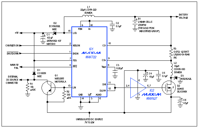
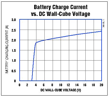
In the portable-system power supply of Figure 1, L2 and Q2 are part of an unorthodox battery-charger configuration for the auxiliary switch-mode output (which normally generates a negative bias voltage for LCDs). Combining the battery charger with a 5V VCC supply offers three advantages over alternative circuits. First, the battery can be recharged without interrupting the system. Second, the high-side current-sense resistor dissipates power only during the charge cycle (conventional low-side sense resistors remain in the ground-return path for all modes of operation). Third, the efficient switch-mode operation requires no heatsink, allowing an all-surface-mount construction.  Figure 1.Suitable for palmtop computers and other portable systems, this power supply can recharge the battery while maintaining an uninterrupted 5V VCC. VCC power is normally obtained from a wall cube or other unregulated DC source, via the linear-regulator action of Q1. When this voltage source is removed, IC1 automatically activates an external switching regulator (L1 and D2), which maintains an uninterrupted output by boosting the battery voltage to 5V. Battery-charger operation depends on intervention by the microprocessor that normally controls such circuits. The µP monitors battery voltage (via an on-board or external A/D converter) and, when necessary, pulls NEGON high (pin 2) to command a charging sequence. IC1 then toggles Q1 at approximately 300kHz, such that the average current through R3 is about 2A. When the µP senses full charge (indicated by a change in slope of the charging voltage), it terminates the charge by driving NEGON low. Charging current is regulated indirectly by an internal comparator that causes Q2 to switch off (for 1µs) when the voltage across R3 exceeds a threshold of 200mV. Higher wall-cube voltage causes a steeper inductor-current ramp, producing a steeper sense-resistor voltage ramp, which allows higher peak inductor currents (IPEAK) during the comparator's fixed propagation delay. The result is a slight increase in average charging current with the applied DC voltage (Figure 2).  Figure 2. Available charging current increases slightly with the applied DC voltage in Figure 1. Charging current is more strongly influenced by the inductor (L2) and current-sense resistor (R3). The equation for ICHARGE is simplified by the inductor's continuous-conduction mode of operation (inductor current remains non-zero during each cycle): ICHARGE = IPEAK -1/2 tOFF(VBATT + VDIODE)/L2, where tOFF = 1µs and IPEAK = 0.2/R1. In Figure 1, therefore: ICHARGE = 0.2/0.09 -1/210-6(2V + 0.45V)/10-6 = 2.09A. A related idea appeared in EDN, December 9, 1993, p 64. |
|
PRODUCTS •
DESIGN •
SUPPORT • SALES • ABOUT
MAXIM HOME • EMPLOYMENT • CONTACT US • JAPANESE • CHINESE |
|
Copyright
© 2000 Maxim Integrated Products |